DESCRIPTION
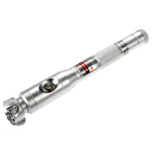
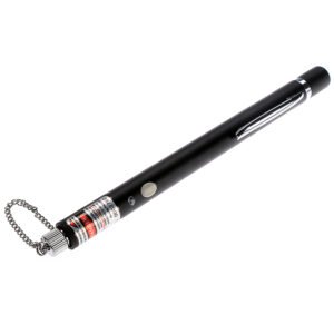
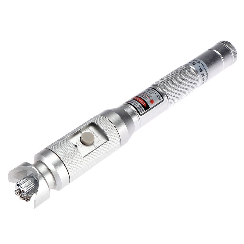
The HTO9V22 Visual Fault Locator (VFL) is designed to detect fiber breakpoints, fiber leaks, poor connections, and stress points. It can be operated in either CW mode or in pulsed mode. Available in multiple output powers (5mW to 50mW) for a wide range of testing needs. Featuring a built-in laser protection device and robust aluminum housing, it ensures safe, reliable, and accurate fault detection for fiber optic engineers and maintenance teams. However, they are not recommended for use with dark-colored or armored cables.
Engineering Suitability & Selection Boundaries
- When This Product Is the Right Choice
- Typically selected when teams need flexible output power options (5–50mW) to match different troubleshooting spans and on-site visibility conditions.
- Commonly suitable when field work requires an added layer of operational control, and the built-in laser protection device aligns with site safety routines.
- Usually fits workflows standardized around 2.5mm interfaces (SC/FC/ST), where adapter dependency can be minimized.
- Often chosen when technicians rely on both CW and pulse modes to improve fault visibility under varying ambient light and access conditions.
- Typically useful for maintenance scenarios focused on quickly locating breakpoints, leakage, stress points, and poor connections during service troubleshooting.
- When This Product May NOT Be Suitable
- May not be suitable in environments where Class IIIB handling controls cannot be consistently enforced, even with a protection mechanism in place.
- May not be appropriate when most daily work is on LC (1.25mm) ports and the team is not prepared to manage converter/adapter availability in every kit.
- Usually not recommended for troubleshooting on dark-colored or armored cables, where visible leakage indication may be unreliable or harder to interpret.
- May be less suitable for teams that want a single fixed behavior and prefer to avoid power-level and pulse-frequency selection, which can introduce operator-to-operator inconsistency.
- Common Selection Mistakes to Avoid
- Choosing the highest power variant by default, without matching output level to the job scope and the site’s laser handling practices.
- Assuming the protection device eliminates the need for disciplined operation in shared spaces, rather than treating it as an additional safeguard.
- Treating “universal interface” as native LC support, without planning for the 1.25mm conversion adapter in field kits.
- Ignoring the stated limitation on dark-colored or armored cables and expecting the same visibility behavior as standard jacketed fiber.
- Mixing CW/pulse and different pulse frequencies across technicians without a shared usage habit, leading to inconsistent troubleshooting outcomes.
FEATURE DETAILS

- Multi-Power Output Options: Available from 5mW to 50mW, allowing users to select suitable power levels.
- Laser Protection Device: Integrated laser safety mechanism, ensuring safe operation in field environments.
- Dual Operating Modes: Supports both CW and Pulsed modes for flexible visual fault identification in different fiber conditions.
- Universal Fiber Interface: Equipped with 2.5mm universal connector interfaces (1.25mm optional) for versatile testing.
- Durable and Portable Design: Constructed from high-strength aluminum alloy, drop-resistant and dust-proof design.
PRODUCT SPECIFICATIONS
| Parameter | Details |
| Model | HTO9V22 |
| Central Wavelength | 650nm±10nm (635nm is available on request) |
| Emitter Type | FP-LD |
| Output Power | 5mW (Laser Range≥5km) 10mW (Laser Range≥10km) 20mW (Laser Range≥20km) 30mW (Laser Range≥30km) 40mW (Laser Range≥35km) 50mW (Laser Range≥40km) |
| Optical Connector | 2.5mm universal connector, for 1.25mm connectors, FC (Male)-LC (Female) converter can be provided on request |
| Operating Model | Both CW and Pulse available |
| Pulse Frequency | 2Hz to 3Hz / 9Hz |
| Power Supply | 2AA alkaline batteries |
| Long Battery Life | Up to 60 hours |
| Operating Temperature | -20℃ to 60℃ |
| Storage Temperature | -40℃ to 85℃ |
| Dimension | 25 x 195mm |
| Weight | 169g (without battery) |
APPLICATION DETAILS
- Telecom Maintenance: Detects fiber faults in ODN and access networks during service troubleshooting.
- FTTH Installation: Identifies fiber breaks and poor connections during fiber drop cable setup.
- Data Center Operations: Helps locate bad patch cords or fiber paths within rack systems.
- Laboratory Testing: Used for visual continuity verification during connector polishing or assembly.
- On-Site Fiber Repair: Enables quick detection and isolation of faults in live fiber networks.
FAQ
Q1: What is the working wavelength of this visual fault locator?
A1: It emits a visible red laser at 650 nm for easy fault detection with the naked eye.
Q2: How far can it detect fiber breaks?
A2: Depending on the output power, it can detect ≥40 km for 50mW versions.
Q3: Is it safe for the eyes?
A3: Yes, it includes a laser protection device and should be used with caution following Class IIIB safety standards.
Q4: What connector types are supported?
A4: It supports 2.5mm interfaces (SC, FC, ST) and 1.25mm (LC) with adapters.
Q5: What are the available power options?
A5: Available in 5mW, 10mW, 20mW, 30mW, and 50mW models for different application ranges.
Q6: Can I use it on both single-mode and multimode fibers?
A6: Yes, it’s compatible with both fiber types.
Q7: Is it suitable for outdoor fieldwork?
A7: Yes, its aluminum alloy housing ensures durability and stability under field conditions.